Frequency Translations
RF/IF Local Oscillator (Analog Domain)
Radio-frequency (RF) or intermediate frequency (IF) local oscillator (mixer) is an active or passive analog device that converts a signal from one frequency to another. It can do frequency upconversion or downconversion of the input signal. A frequency mixer is a 3-port electronic circuit. Two of the ports are “input” ports and the remaining port is an “output” port. These three ports are the radio frequency (RF) input, the local oscillator (LO) input (reference signal), and the intermediate frequency (IF) output.
The ideal mixer “mixes” the two input signals such that the output signal frequency is either the sum (or difference) frequency of the inputs, depending on if a signal is being up or downconverted.
Fundamentally, “mixing” of two input signals is done by their multiplication. From implementation perspective, multiplication of two signals is non-linear operation, and RF mixers cannot be realized by linear-time-invariant (LTI) components or circuits. Instead, the translation is achieved by either time varying or non-linear circuits, e.g., diodes.
But, let’s keep on fundamentals and demonstrate “mixing” as simple math and some spectrum images. Assume we have input cosine signal with frequency \(\omega_{IN}\) and LO cosine signal with frequency \(\omega_{LO}\)
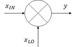
Fig. 1. A block representation of a mixer
Both input signals can be shown in frequency domain as
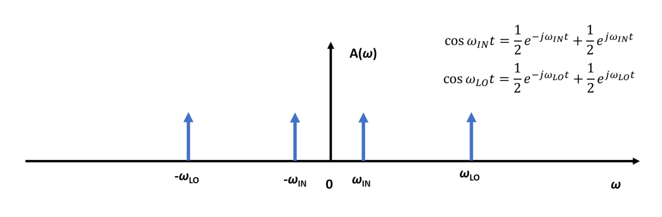
Fig. 2. Original spectra of the two signals.
If we do multiplication of the input signals
and apply product-to-sum identity for trigonometric functions, we obtain output signal and its spectrum
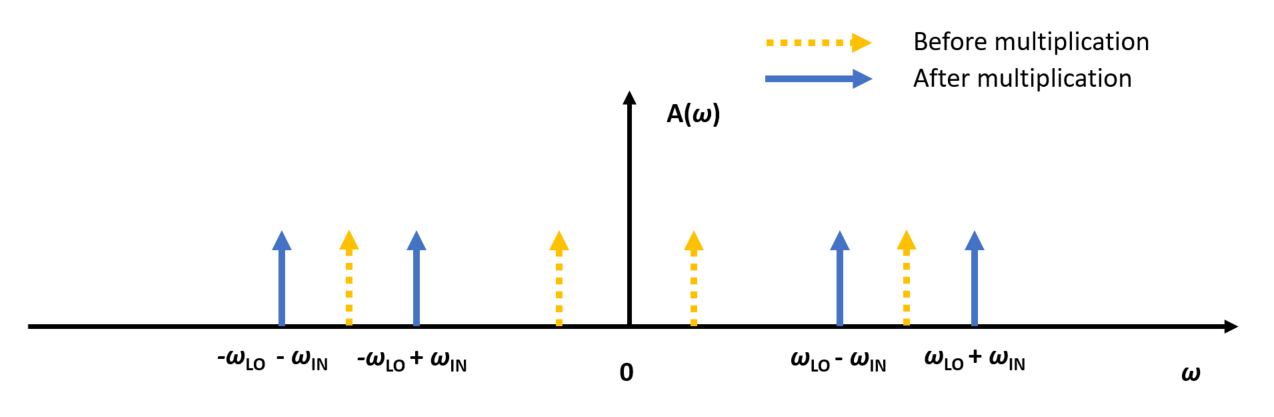
Fig. 3. Spectra after multiplication.
These two signal components are called the upper and lower sideband. Filtering out one of them, let’s say the lower sideband, we get the signal transposed in frequency. And that’s our final upconverted signal! Similar story you can do for downconversion, you can try it yourself :)
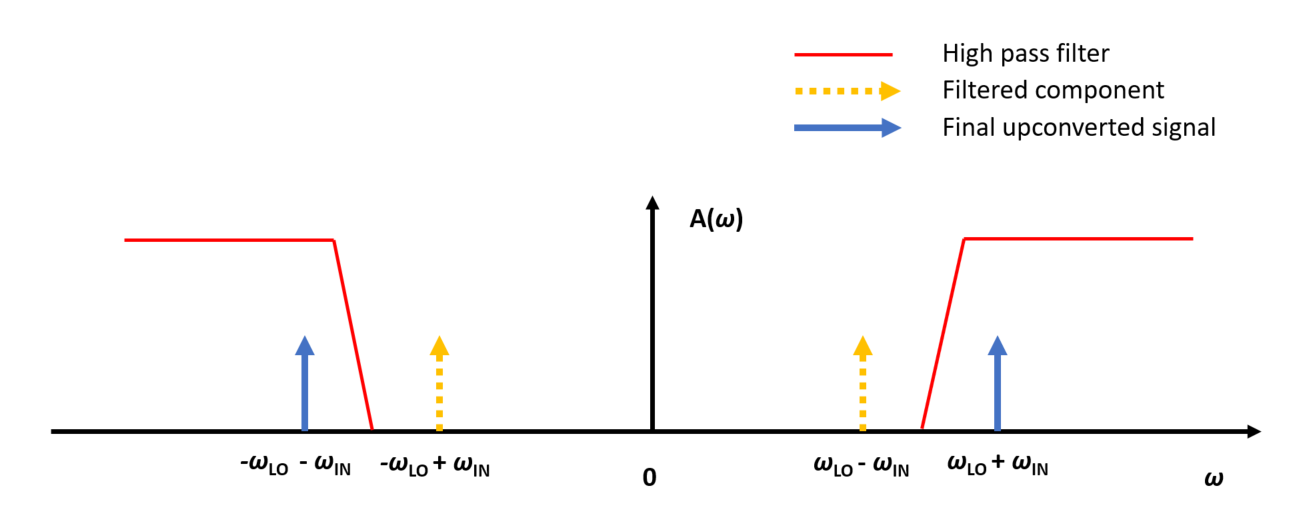
Fig. 4. Filtering the spectrum.
Numerically Controlled Oscillator (Digital Domain)
Numerically controlled oscillator (NCO) is component in digital domain that implements frequency downconversion and upconversion on discrete signals. The basic idea is quite simple, assume that we have analog signal for mixing
If this signal is sampled with frequency \(f_{s}=1/T_{s}\), we get discrete time slots with corresponding oscillator values
Discrete values of signal \(x[n]\) represent output samples of numerically controlled oscillator. Notice that in this case, we are limited with value for frequency translation \(f_0\), due to Nyquist-Shannon theorem, in the range \([-f_{s}/2,f_{s}/2]\). Try to pick for example frequency translation value \(f_0=f_s\). What is the shape of signal \(x[n]\) in that case? Furthermore, in practical cases there is also need to do “complex mixing” of the digital signal. In that case, mixer signal has the form