Filtering in Digital Domain
From a signal processing point of view, filtering means suppressing the unwanted frequency components of the signal, thus extracting the useful components. Generally, any system that changes the input signal in some way can be called a filter.
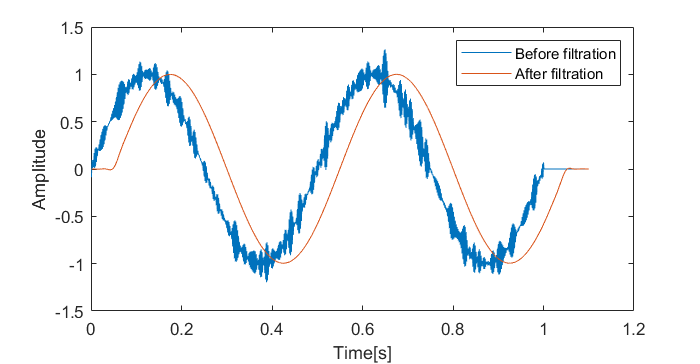
Fig. 1 .Filtration of a noisy signal.
- The most basic classification of filters:
- Low-pass filter – pass low frequencies, attenuate high frequencies
- High-pass filter – pass high frequencies, attenuate low frequencies
- Band-pass filter – pass only frequencies inside a specific area (band)
- Band-stop filter - attenuate only frequencies inside a specific band
All filters are defined by their transfer function which defines the relation between input and output signals in frequency domain \(H_k=Y_k/X_k\) . Depending on the signal type, filters can be analog or digital. Analog filters are always implemented by physical components, whereas digital filters can be implemented in multiple ways by hardware or software. There are two main types of digital filters:
- Infinite impulse response (IIR):
- IIR filters are also called recursive filters because they are defined by the recursive formula which gives the response of infinite length.
- Finite impulse response (FIR):
- Determined by the finite number of coefficients of the impulse response \(h_n\). Impulse response is defined by the response of FIR filter to the short pulse (Kronecker delta)
Finite Impulse Response (FIR) Filters
FIR filter of the order \(N+1\) has \(N\) coefficients and it’s impulse response and transfer function are connected by:
Filtering of is performed by convolution of the signal and the impulse response.
Convolution can be described as an operation which modifies one function by the shape of another. Changing the order of input functions produces the same result. The operation can be easily visualized, as shown in the linked video. Filtering can also be performed in frequency domain by multiplication of the signal spectrum by the filter’s frequency response.
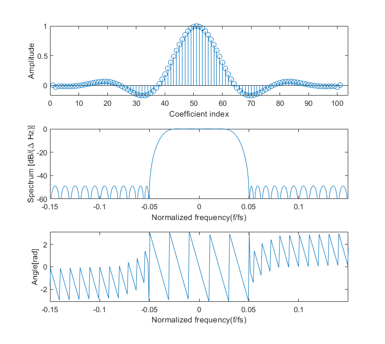
FIR filter of a 101-th order; coefficients, magnitude and phase response.
Linear Phase
Arising from the properties of convolution, filtration inserts the delay in the output signal which is proportional to the filter size (order). According to the time shifting property of Fourier transform, delay by certain number of samples in time domain will cause a phase shift in frequency domain. We introduce the term group delay, which is defined as derivation of the phase response at a given frequency \(\omega\);
To preserve the shape of the original signal, we have to make sure that our filter has constant group delay. That means that the phase response has to be linear so its derivation will be constant. According to the Fourier transform properties, that means that the filter coefficients have to be symmetrical around the center sample or pair of samples. Thus, it can be found that the delay of the signal is equal to \(N/2\)
Complex FIR Filters
Similarly to the signals, filters can also be defined by the complex coefficients. That will cause asymmetrical frequency response and selective filtering of positive and negative frequencies.